
Key features/benefits
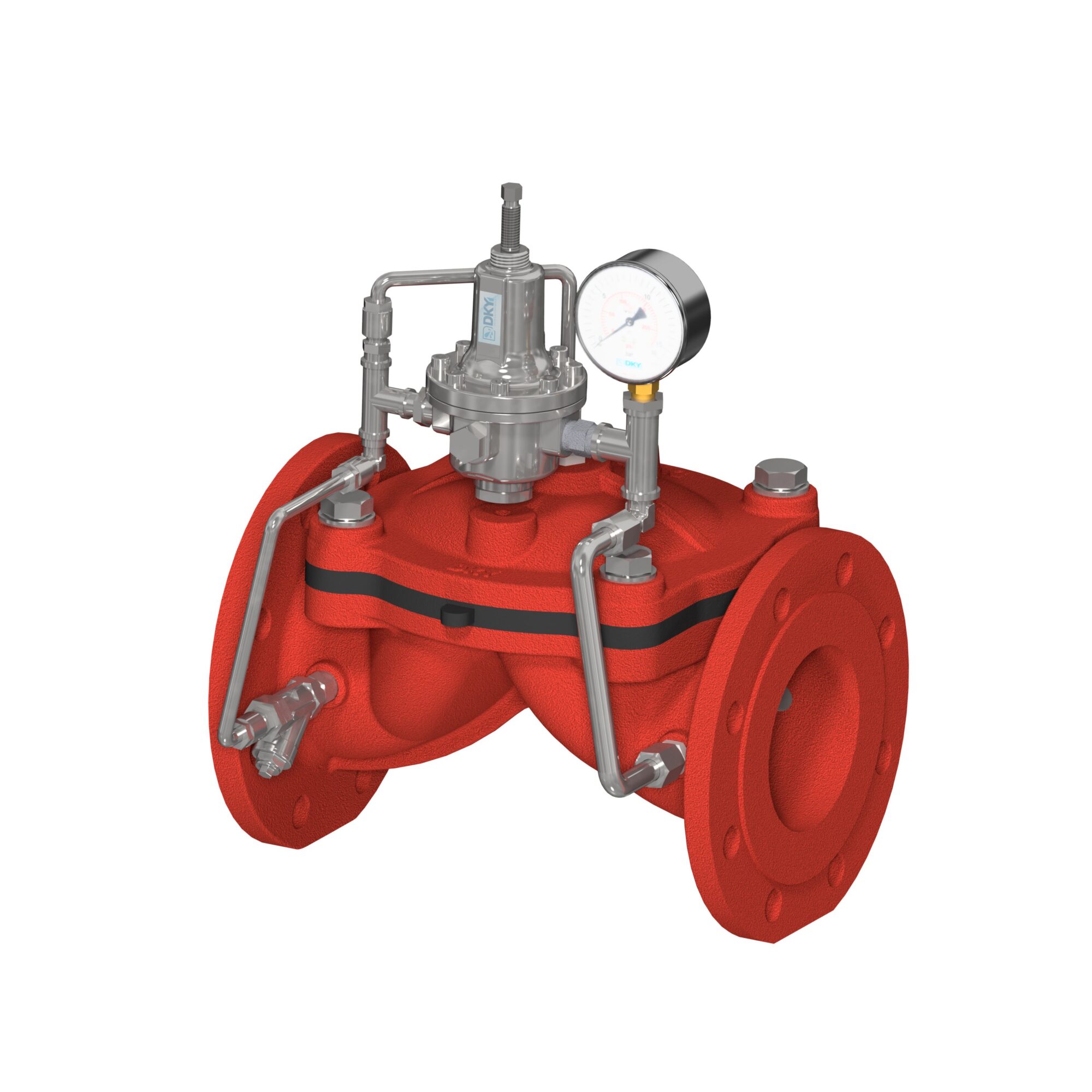
The DRF 80FP combines a unique design and simplicity into a fire protection systems pressure relief valve. This diaphragm operated, pilot controlled, hydraulic valve will maintain a constant pressure of the fire-extinguishing network, regardless of flow demand. Whenever the system pressure rises above preset level, the valve opens and relieves excess of flow and pressure to the atmosphere, maintaining the system running at a stable, required pressure. The DRF 80 FP features “no-spring” diaphragm and controlled by a 2-way, spring-loaded pilot valve to ensure maximum accuracy of the line pressure and fast reaction.
Operation: “The RAF 80FP is normally installed on-line in a Tee configuration, after the fire pump and before the system’s check valve. As line pressure exceeds the set point, It shall relief excess flow and pressure to the sump maintaining the desired system’s preset pressure. When demand of the fire system drops to a minimum, the Raf 80 FP will maintain fully open, relieving 100% of the pump’s flow capacity. The check valve will then close, isolating the lines from the pump. The pump will shut off safely, avoiding the risk of a surge. As the pump shuts off, the relief valve will slowly come to a close. ”
“The DRF 60FP is a diaphragm operated, pilot controlled hydraulic valve to maintain a constant downstream pressure on the fire-extinguishing network, regardless of flow demand. Whenever the system pressure tends to rise above preset level, the valve throttles further and reduces the excess pressure to the required set value at a stable regulation. The DRF 60FP features “no-spring” diaphragm and controlled by a 2-way, spring-loaded pilot valve to ensure maximum accuracy of the line pressure and fast reaction.”
“The DRF 60FP is normally installed in-line, after the fire pump and after the system’s check valve. As line pressure exceeds the set point, it shall reduce the pumped pressure to the system’s preset line pressure. DRF 60FP automatically maintains the outlet “set pressure” (static and residual) constant regardless of fluctuations in the higher pressure inlet line or varying flow rate. Different pressure zones are achieved statically from the same high pressure main line. ”
| TECHICAL INFORMATION | |||||
| Diameter | DN50 – DN200 | ||||
| Pressure | PN10 – 16 | ||||
| Body Material | EN GJS 400-15 | ||||
| Diaphragm Material | Nylon Fiber Reinforced Rubber | ||||
| Pilot Material | AISI304 | ||||
| Accessory Material | AISI304 | ||||
| Working Pressure | 12 bar (Maximum) | ||||
| Flange Standard | EN 1092 – 2 | ||||
| Test Standard | EN 12266 – 1 | ||||
| Operating Temperature | 4°C … +65°C | ||||
| Coating | Thermoplastic, Electrostatic Epoxy | ||||
| Diameters | |||||||
| DN | PN | DRF80 FP | DRF60 FP | ||||
| L | H | W | L | H | W | ||
| DN50 | 10 – 16 | 205 | ~350 | ~245 | 205 | ~330 | ~240 |
| DN65 | 10 – 16 | 216 | ~370 | ~270 | 216 | ~350 | ~260 |
| DN80 | 10 – 16 | 283 | ~390 | ~280 | 283 | ~380 | ~280 |
| DN100 | 10 – 16 | 305 | ~420 | ~300 | 305 | ~410 | ~300 |
| DN150 | 10 – 16 | 406 | ~490 | ~360 | 406 | ~470 | ~390 |
| DN200 | 10 – 16 | 521 | ~570 | ~430 | 521 | ~550 | ~430 |


